


 Home
Ultrasonic Tube Sealing for Data Center Liquid Cooling Loops | Borude
November. 04,2026
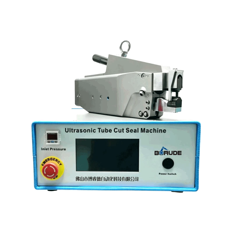
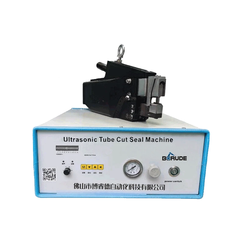
Direct-to-chip liquid cooling turned a refrigerant practice into a data center practice. A rack of accelerated servers can now draw well over 100 kW from a footprint that used to hold 15 kW. The replacement for air is a closed loop of coolant running through cold plates, quick disconnects, manifolds and a coolant distribution unit — dozens of small-bore copper joints inside a room full of hardware that costs more per square meter than any factory floor. Every one of those joints is a leak candidate, and the industry is discovering that a brazed joint carries two problems, not one: it can leak, and the process that made it leaves residue inside the loop. This is where an ultrasonic tube sealer enters the thermal manufacturing line.
1. Why a Liquid Cooling Loop Punishes Brazed Joints
A refrigerant circuit in a refrigerator is a sealed system nobody opens for a decade. A data center cooling loop is the opposite: assembled in a factory, shipped, installed, pressure-tested on site, filled with glycol, then drained and refilled by technicians more than once over its life. That duty cycle attacks a brazed joint from four directions at once. Pressure swings between vacuum evacuation and hydrostatic test stress the joint in both directions. Thermal cycling from a cold start to 45 °C return coolant works the filler metal against the copper. Glycol mixtures at slightly elevated temperature are far more aggressive to a joint with residual flux than plain water. And any joint that weeps does not simply drip — it wets a connector, a PCB edge or a busbar, and the resulting repair bill is measured in servers, not in tubes.
The second problem is invisible and often worse. Brazing needs flux, and flux residue inside a closed loop becomes particulate in the coolant: it settles in the narrowest passages of a microchannel cold plate, loads the loop filter, accelerates pump wear, and slowly raises the thermal resistance the whole system was built to guarantee. A tube sealed by an ultrasonic tube sealer introduces no flux, no filler alloy and no oxide scale, because nothing is melted and nothing is added — the tube wall itself is folded and fused into a solid-state joint, so the inside of the loop stays as clean as the tubing arrived.
2. What Ultrasound Does to a Copper Tube End
The mechanics are simple to describe and hard to execute well. The tube end is gripped in a crimping die while a sonotrode presses against it at 20 kHz. The high-frequency shear breaks the surface oxide and brings clean copper into intimate contact; under clamping force the interface recrystallizes into a continuous metallic bond, and the die closes the tube into a sealed bead in the same cycle. Cycle time runs two to five seconds for typical 4–10 mm copper tube. Because energy is delivered only at the weld interface, the tube shank 20 mm away stays close to room temperature — which matters when that shank sits next to a plastic quick disconnect, a temperature sensor or a bonded hose barb.
For liquid cooling work, three consequences are commercially decisive. There is no heat-affected zone large enough to anneal a formed bend or soften a flare. There is no post-weld cleaning step, no pickling, no nitrogen purge and no flux inventory to lot-control. And the joint is a solid copper section, so burst and pull strength come from the tube wall rather than from a filler alloy whose quality depends on the operator's hand that shift.

3. Where the Process Sits in a CDU or Manifold Build
Liquid cooling hardware reaches the sealing station at several distinct points, each with its own requirement. Charging and fill ports on a coolant distribution unit are closed after evacuation and charge, and must hold while the unit is transported. Blind ends on supply and return manifolds are sealed at the bench, long before the manifold sees pressure. Cold plate tails and sensor stubs are sealed immediately after the leak check, because a plate that passes helium and then gets a torch nearby may not pass again. Service and drain ports on rack-level manifolds are closed last, after the assembly has been flushed.
Sequencing the seal after the leak test is the standard rule, and it is why a bench-top copper tube sealing machine belongs next to the test station rather than in a separate welding cell. Operators test, seal and record without a second handling step or a queue in front of a torch booth.
4. Specification Checklist for a Thermal Production Line
Buyers evaluating an ultrasonic metal welder for liquid cooling work should pin down six things before comparing quotations. First, the tube: outside diameter, wall thickness and temper, with C12200 phosphor-deoxidized copper as the baseline and thin-wall or aluminum variants called out separately, because they need different tooling and recipes. Second, the control tier — closed-loop amplitude, force and displacement control is not a luxury on a line that must document every joint. Third, data output: energy, force, displacement and time per weld, exportable as CSV or through an interface your MES can read. Fourth, tooling economics: welds per regrind on your exact tube, replacement horn and anvil cost, regrind turnaround. Fifth, cleanliness confirmed in writing: no flux, no filler, no coolant contamination path. Sixth, the trial protocol — your real manifold stub or cold plate tail, welded, sectioned and pressure-tested before any purchase order.

5. Leak Rate, Cycling and Fluid Compatibility
Acceptance for a data center loop is normally written as a helium leak rate under vacuum or pressure, followed by a pressure-decay hold and a burst margin requirement on the sealed end. A solid-state ultrasonic weld passes these because there is no porosity, no incomplete fusion line and no flux inclusion to act as a leak path; the bead is a continuous copper section produced by the same stored recipe every cycle. Where a brazed joint's quality is inferred from a visual inspection, an ultrasonic joint's quality is inferred from the parameter curve that produced it — a materially different audit position.
Long-term reliability follows from the same absence of residue. Without chloride-bearing flux trapped against the tube wall, there is no initiation site for stress-corrosion cracking under a glycol-wetted surface; without a dissimilar filler alloy, there is no galvanic couple to drive preferential attack at the joint. Thermal cycling between cold standby and 45 °C return coolant, plus the vibration of a rack fan wall, is exactly the regime where a clean, fully bonded copper joint is at its strongest.
Contact Borude for a Liquid Cooling Tube Sealing Trial
If your line builds cold plates, manifolds, coolant distribution units or rack-level thermal hardware, Borude can seal your own copper tube samples and return sectioned joints, burst data and weld parameter records for your qualification file. Review our ultrasonic welding applications, or send a sample tube and your leak-rate specification through the contact page to start an application trial.


